Tompson Patent Lock
William Tompson’s lock design was first patented on 29th December 1808. Its double-action movement is very similar to the earlier Turner Patent lock, whereby the bolt links and central moving peg initially raise beyond the surface of the lock plate, with then only the links sliding over to the left and into the locked position.
Tompson Patent locks are more often found in writing boxes; their design enables the lock plate surface to be flat and unimpeded when in the unlocked position. This differs from Bramah’s writing box locks which have their links and locating pins protruding through the lock plate surface whether in the locked or unlocked position.
The lock plate surfaces bear the name ‘Tompson’, usually accompanied by ‘Bir.M’ (short for Birmingham – the location of his manufactory) and ‘GR [George Rex] Patent’ beneath the monarch’s crown. These texts are laid out in a curved format, reminiscent once again of the Turner Patent lock.
Some Tompson Patent locks are fitted with a decorative cast brass front escutcheon; the keyhole of which is set within the design of the royal coat of arms, partially surrounded by ‘Tompson Patent’ in raised lettering.

Tompson Patent lock and key

Overhead view of a Tompson Patent lock plate stamped with ‘Tompson Bir.M’ (Birmingham) and ‘GR Patent’ beneath a crown.

Interior of a Tompson Patent lock (in its unlocked position) with the bolt, drill pin, circular ward and central moving peg in view.

Interior of a Tompson Patent lock (in its locked position) with the bolt, drill pin, circular ward, lever spring and central moving peg in view.

Interior of a Tompson Patent lock with the bolt removed. The drill pin, circular ward, two sprung levers and central moving peg are in view.

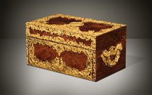
A Tompson Patent lock fitted into an antique jewellery box in rosewood with engraved brass inlay.
Operating a Tompson Patent Lock
- The key enters the front lock aperture; the side wards of the key tip are incised to clear the circular ward. The purpose of the circular ward is to obstruct any foreign key from operating the lock.
- As the key turns anti-clockwise, the bit to the key shank engages with the first sprung lever; this raises the bolt so that the links and the central moving peg simultaneously protrude from the surface of the lock plate.
- As the key continues its turn (from about the 12 o’clock position), it makes contact with the second sprung lever and carries the sliding bolt over towards the left; the pierced rectangular gating (the lanket) on the bolt allows the central moving peg to be independent and undisturbed by this sliding action, thus remaining fixed in place.
- The mechanism is now in its locked position.
- To unlock the mechanism, the key is re-inserted and turned clockwise by 360 degrees. The links and central moving peg fully retract to the same level plane as the surface of the lock plate. The key can now be withdrawn from the front lock aperture.

Acknowledgement of William Tompson’s lock patent taken from the ‘Titles of Patents of Invention Chronologically Arranged From March 2, 1617 To October 1, 1852’.
 Price On Application