Turner Patent Lock
The Turner Patent lock, initially patented in 1798, can be disassembled into the following parts:
- A brass back and lock surface plate. The lock surface plate is engraved with ‘Turner’s’, ‘Patent’ and ‘W-Hampton’ (Wolverhampton), accompanied by crowns representing the monarch.
- A brass lock mount. The circumference of the front keyhole aperture is engraved with ‘Turner’s Patent’ accompanied by a crown. A fixed circular rim to the rear of the mount has incised apertures at either side.
- A brass rimmed wheel, or ‘moving cup’. This rotating wheel connects directly over the fixed circular rim, and has corresponding incised side apertures. An incised rectangular aperture to the rear of the rimmed wheel engages with a stud on the sliding bolt.
- A steel sliding bolt with a central moving peg. The central moving peg is attached to the sliding bolt by a pin; this allows the sliding bolt to move across freely without disturbing the central moving peg.
- A bullet ward. This is a steel disc with a ‘tooth’ that protrudes over the keyhole shaped incision.
- Two tumblers, or ‘spring bolts’. The bullet ward is sandwiched by both spring bolts and housed within the fixed circular rim to the rear of the lock mount. The fine springs of the spring bolts are held in place by grooves running around the inner circumference of the fixed circular rim. In their ‘relaxed’ position, the arms of the spring bolts protrude through the incised side apertures of the fixed circular rim and rimmed wheel, effectively inhibiting the rimmed wheel’s ability to rotate.
- A key with an incised tip to the shank. The incised tip allows the key to pass through the ‘toothed’ bullet ward.

Antique Turner Patent lock disassembled.

Antique Turner Patent lock disassembled: View of the brass back and lock surface plate, steel sliding bolt with a central moving peg, drill pin, brass rimmed wheel, spring bolt, and bullet ward.

Antique Turner Patent lock disassembled: Rear view of the brass lock mount with the fixed circular rim visible, bullet ward, and spring bolt.

Antique Turner Patent lock disassembled: Rear view of the brass lock mount and rimmed wheel.

Antique Turner Patent lock in its unlocked position.

Antique Turner Patent lock in its locked position.

Antique Turner Patent lock key.

Overhead view of an antique Turner Patent lock.

Link plate from an antique Turner Patent lock.

Front aperture of an antique Turner Patent lock.

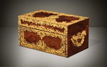
Antique officer’s box in Cuban mahogany with a Turner Patent lock, by David Edwards.
Operating a Turner Patent Lock
- The key enters the front lock aperture.
- As the key turns anti-clockwise, the bits to the key shank engage with the two spring bolts; the springs of the spring bolts contract, withdrawing their arms from the incised side apertures of the fixed circular rim and rimmed wheel. The rimmed wheel, now uninhibited by the arms, can rotate with the aid of the key.
- As the wheel rotates, it carries the sliding bolt upwards and over towards the left, whilst simultaneously raising the central moving peg directly upwards.
- The mechanism is now in its locked position.
- To unlock the mechanism, the key is re-inserted and turned clockwise by 360 degrees to its initial insertion point. The key can now be withdrawn from the front lock aperture.
 Price On Application